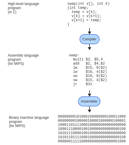
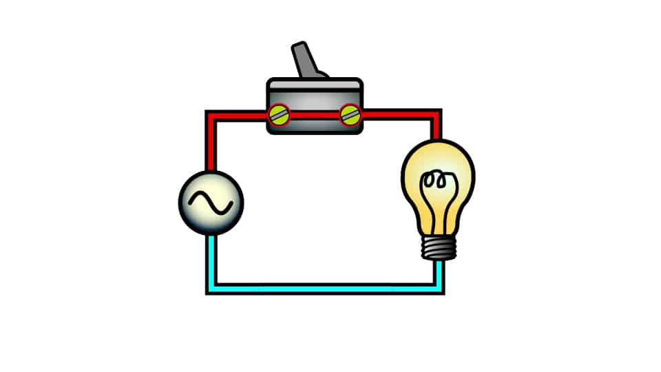
## Gates, Truth Tables, and # Boolean Algebra --- CS 130 // 2021-11-01 <!--=====================================================================--> ## Administrivia - Debrief on Exam 2 - <!-- .element: class="fragment"--> Readings for the next few weeks are on Blackboard (Appendix C of our textbook) <!--=====================================================================--> # Questions ## ...about anything? <!--=====================================================================--> # Course Themes <!-- .slide: data-background="#004477" --> <!--=====================================================================--> ## Overarching Theme - Learning how a high-level program is actually executed on your computer's processor <!---------------------------------->  <!----------------------------------> ## Trajectory of the Course 1. The C Programming Language 2. Assembly language programming 3. **Digital logic** 4. Processor architecture <!--=====================================================================--> ## Basic CPU Operations - Recall that most operations operate on one or more 32-bit registers + <!-- .element: class="fragment"--> `add $s0,` `$s1`, `$s2` takes two 32-bit numbers, adds them up, and produces a new 32-bit number - <!-- .element: class="fragment"--> How can we build a machine that takes 0s and 1s as input and produces 0s and 1s as output? <!--=====================================================================--> # Digital Logic <!-- .slide: data-background="#004477" --> NOTE: Discuss how hard electrical engineering is and why it is so useful to focus on the simplicity of digital logic <!--=====================================================================--> ## Transistors - CPU instructions are implemented with nanoscale switches called **transistors** <div class="twocolumn"> <div>  <!-- .element: class="fragment"--> </div> <div> You can think of a transistor as a "switch" with states "on" and "off" <!-- .element: class="fragment"--> </div> </div> <!----------------------------------> ## Digital Logic - Learning about electricity, capacitors, resistors, is beyond the scope of this course - <!-- .element: class="fragment"--> For now, it is useful to abstract away the details of electrical engineering - <!-- .element: class="fragment"--> We will think about circuits in terms of 0s and 1s going through the wires of a circuit <!----------------------------------> ## Input/Output as Voltages <div class="twocolumn"> <div> - The 0s and 1s of our circuits will be "low" and "high" voltages across a wire, similar to a light bulb being "on" and "off" </div> <div>  </div> </div> <!--=====================================================================--> ## Logic Gates - A **logic gate** is an elementary circuit that takes one or more bits as input and produces one or more bits as output - <!-- .element: class="fragment"--> Many of these logic gates can be constructed with one or two transistors <!----------------------------------> ## Name that Gate  --- - <!-- .element: class="fragment"--> An **AND** gate <!----------------------------------> ## Name that Gate  --- - <!-- .element: class="fragment"--> An **OR** gate (inclusive OR) <!----------------------------------> ## Name that Gate  --- - <!-- .element: class="fragment"--> A **NOT** gate <!----------------------------------> ## Name that Gate  --- - <!-- .element: class="fragment"--> A **NAND** gate <!----------------------------------> ## Name that Gate  --- - <!-- .element: class="fragment"--> A **NOR** gate <!----------------------------------> ## Name that Gate  --- - <!-- .element: class="fragment"--> An **XOR** gate (exclusive OR) <!--=====================================================================--> ### What is the truth table for the following circuit? --- <div class="twocolumn" style="font-size: 70%"> <div>  </div> <div> <table> <tbody> <tr> <td>A</td> <td>B</td> <td>C</td> <td>D</td> </tr> <tr> <td>0</td> <td>0</td> <td>0</td> <td> </td> </tr> <tr> <td>0</td> <td>0</td> <td>1</td> <td> </td> </tr> <tr> <td>0</td> <td>1</td> <td>0</td> <td> </td> </tr> <tr> <td>0</td> <td>1</td> <td>1</td> <td> </td> </tr> <tr> <td>1</td> <td>0</td> <td>0</td> <td> </td> </tr> <tr> <td>1</td> <td>0</td> <td>1</td> <td> </td> </tr> <tr> <td>1</td> <td>1</td> <td>0</td> <td> </td> </tr> <tr> <td>1</td> <td>1</td> <td>1</td> <td> </td> </tr> </tbody> </table> </div> </div> <!--=====================================================================--> # Boolean Algebra <!-- .slide: data-background="#004477" --> <!--=====================================================================--> ## Boolean Algebra - We can represent logic gate computations as using **Boolean algebra** + <!-- .element: class="fragment"--> All variables `$A, B, C, \ldots$` are either 0 or 1 + <!-- .element: class="fragment"--> `$A\cdot B$` means the **AND** of `$A$` and `$B$` + <!-- .element: class="fragment"--> `$A+B$` means the **OR** of `$A$` and `$B$` + <!-- .element: class="fragment"--> `$\overline{A}$` means the **NOT** of `$A$` <!----------------------------------> ## Boolean Algebra Practice - Let's convert the Boolean expression `$\overline{A}(B+C)$` into its equivalent logic gate representation --- - <!-- .element: class="fragment"--> **EXERCISE**: Do the same with these: + `$(\overline{A}\cdot\overline{B})+(\overline{C}\cdot\overline{D})$` + `$(A+\overline{C})(\overline{D}+\overline{B})$` + `$A(B+\overline{A}+A)+B\overline{A}$` <!--=====================================================================--> ## Universal Gates - The **NAND** gate and the **NOR** gate are "universal" and can be used to construct every other gate --- - <!-- .element: class="fragment"--> How can we construct a NOT using a NAND? - <!-- .element: class="fragment"--> How can we construct an AND using only NANDs? - <!-- .element: class="fragment"--> How can we construct an OR using only NANDs? - <!-- .element: class="fragment"--> How can we construct an XOR using only NANDs?